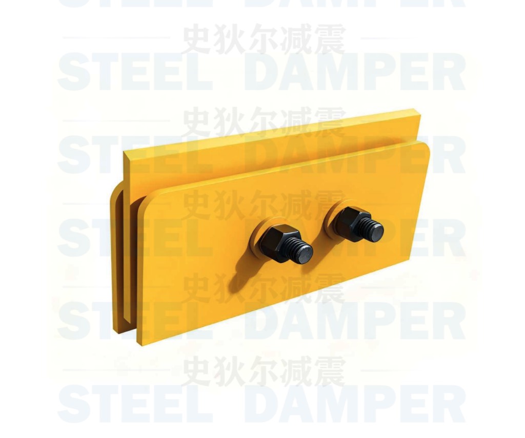
SFD Introduction
A damper that dissipates input energy through frictional sliding between components. It is widely used because of simple construction, stable performance, and large damping force.
SFD Introduction 2
Under normal service loads, SFD provides additional stiffness without sliding. Under moderate and major earthquakes, it slides and dissipates energy through friction work, reducing structural response.
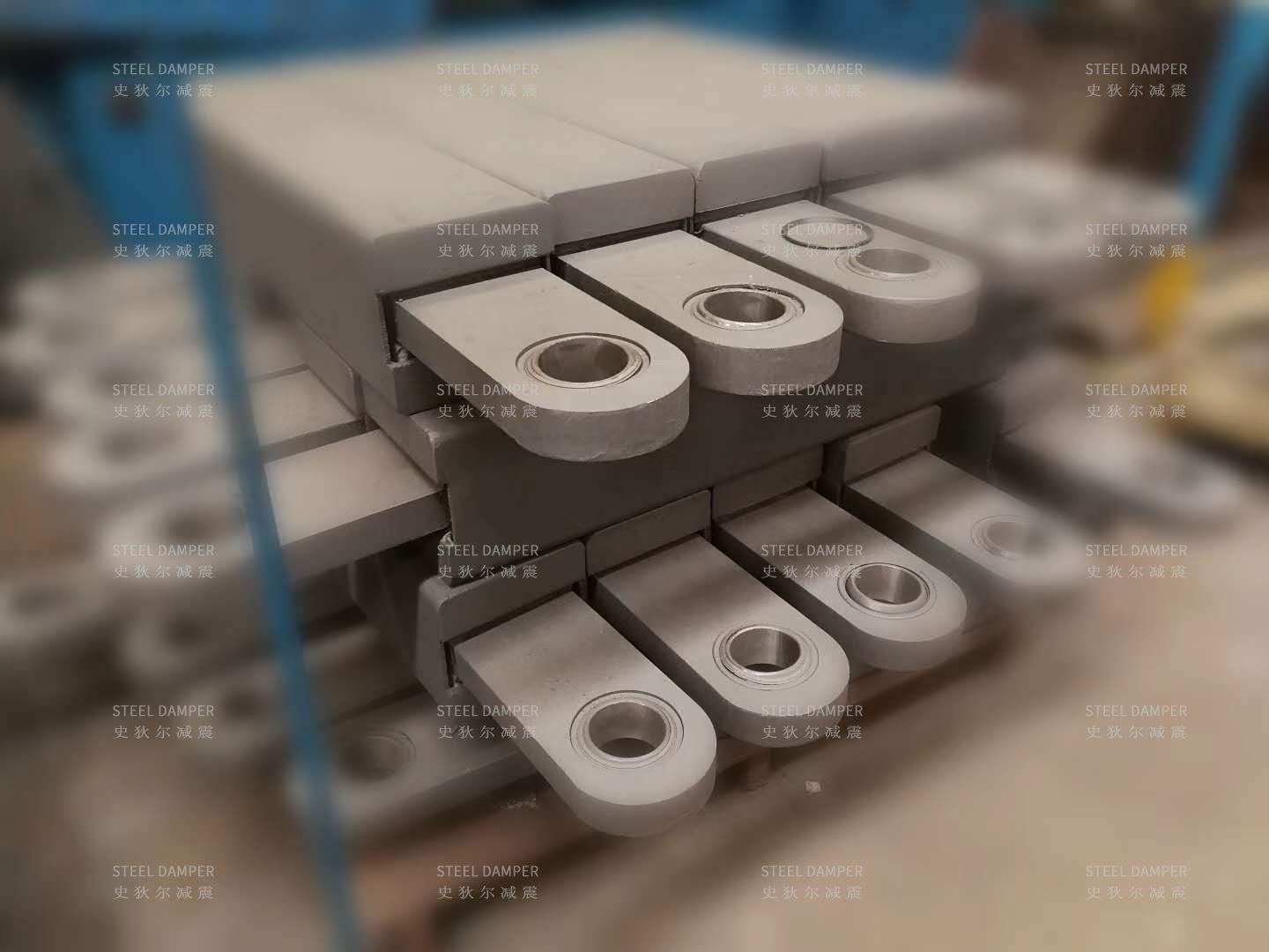
SFD Introduction 3
Friction damper development has produced many forms, including friction energy-dissipation joints and dedicated sliding mechanisms.
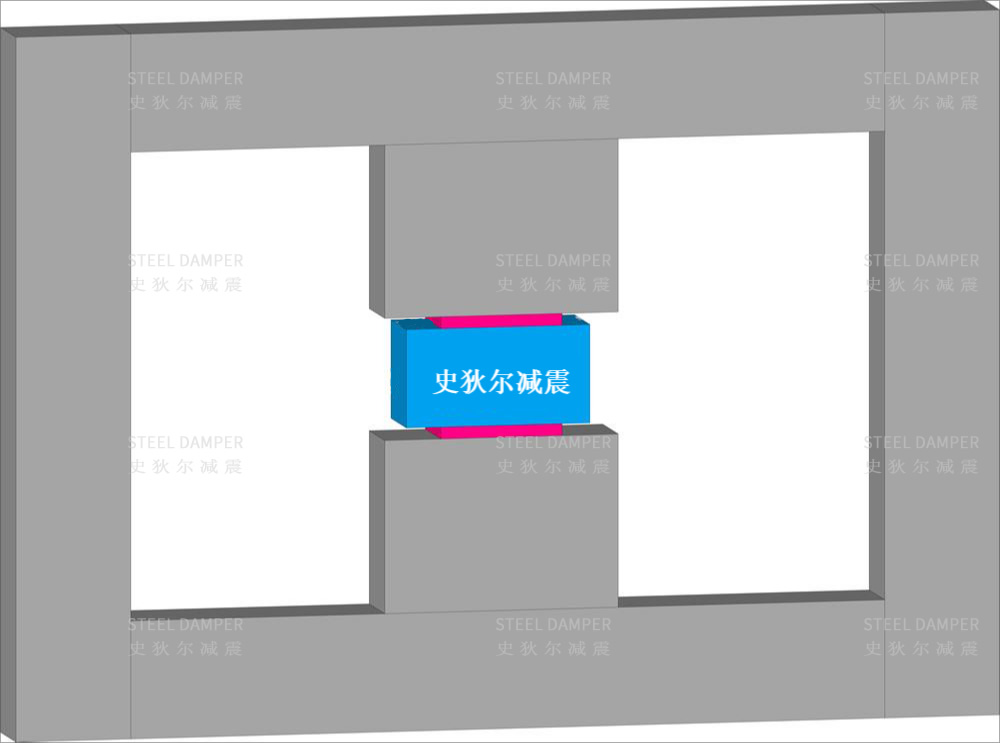
Connection Type
Wall-type connection is flexible and can supplement existing walls without affecting space use.
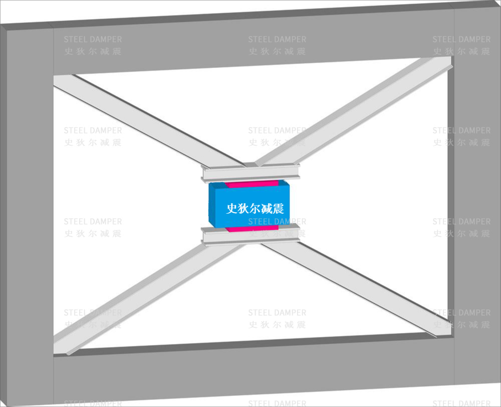
Connection Type 2
Brace-type connection is suitable for new and retrofit projects, with embedded parts placed near beam-column joints for efficient force transfer.

Connection Type 3
Coupling-beam friction dampers are common in shear-wall residential structures, replacing conventional concrete coupling beams.